Reading the SCW9047 Installer Code
 tl;dr: I found an unpopulated header in our SCW9047 alarm panel, figured out that it tapped into an I²C bus, and was able to sniff the “super-secret” Installer Code.
Background
Add me to the long list of people who’ve “inherited” a security system (actually two) in their house, but aren’t (yet?) willing to pay for a monitoring service.
Benign Neglect
What did we do with the unknown system in our house? Ignore it! Believe it or not, this strategy only works for so long. Alarm systems don’t like to be ignored when they’ve got an error, and ours has had several cases where it’s triggered a (repeating) audible fault:
- When the clock is not set, after a long power outage. See also: PG&E “Public Safety Power Shutoffs”
- When a sensor has a low battery. Most of ours use a CR2032 cell, and they’ve been slowly dying.
- When the panel has a low battery. This one was particularly annoying because the marginal battery pack would hit the alerting threshold very early each morning as the temperature inside the house caused the voltage to drop. I’d drag myself out of bed, acknowledge the fault (
*2), and then have to do it all over again the next day because once the house warmed up during the day, the battery voltage rose, reported it was “fine” and the error condition cleared itself. At least until the next morning 😭
This fault -> cleared -> fault cycle was annoying. Could we just maintain a constant temperature 24/7 in the house? Don’t think I didn’t consider it. Instead, I “fixed” it by unplugging the battery pack 🙈. Once it stopped “recovering” every day, I acknowledged the fault one last time and moved on.
Ok, so we weren’t ignoring it
Why put up with 👆? The stupidest reason: when a monitored door or window opened, the panel emits a chime. We got used to that - so much so that when I open a door and don’t hear the chime it feels weird. But I also harbor hope that I’ll get the alarm system working some day. The first step is being able to arm and (more importantly) disarm the panel.
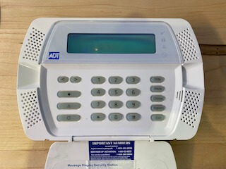
Installer Code / Master Code
I was able to find documentation about our specific panel (SCW9047). But you need to know the secret codes in order to do anything interesting. The Installer Code allows you to view & change the configuration, and there are codes (like the Master Code, used by the homeowner) that are used for disarming the alarm. We didn’t know any of them.
The panel is shipped from the factory with a default installer code. Our panel is manufactured by DSC, but it has ADT branding and they keep sending snail mail to our address with an addressee of “Former ADT Customer”. The internet tells me that ADT is pretty reliable about changing the installer code, and that they’re not inclined to share it with homeowners. I never actually contacted them because it didn’t seem like a good use of my time. I did try the factory default code, which didn’t work (surprise!)
Sidenote: I suspect their business model is similar to subsidized cell phones. The consumer receives a discount up front in exchange for a commitment to pay for the service for a certain amount of time, at which point they’ve been paid back and the consumer should own the hardware. It took far too long for carriers to agree to unlock cell phones once the contract was up, and as a non-party to the original agreement, it feels like bullshit that there’s equipment in my new house that I don’t have full access to.
It may be related to FCC rules for alarm systems running on 433 MHz. §15.231(a)(5) has an exception for “professional installers”, and I could imagine a scenario where they justify a refusal to share the installer code due to that restriction.
Factory / Hardware Reset
Except… I do have access. I have full access, and it’s possible to just reset the hardware and set it up from scratch. Why not do that?
Someone took the time to enroll all of the wireless sensors. If a door or window is open, the panel can tell me which one, by name and location. If you can’t tell, I’d been working on the lazy approach. I really didn’t want to re-enroll all our sensors, and <whatever other setup>. I’d much rather just change the installer and master codes.
Progress!
Ok, so it’s not broken, but it isn’t really “working” either. I finally found the enthusiasm to do more. A year ago, or even 3 months ago, I didn’t have the knowledge necessary for today’s progress. It was nice seeing the puzzle pieces come together.
🔌 Power
 This panel uses a 16.5V AC power supply. I really didn’t want to crawl around in our basement to unplug and pull the transformer out, but I did want to move the panel to my desk. I remembered that 7.2V DC battery inside the alarm panel, and reasoned that if the panel can run from battery backup, I should be able to plug it into my bench power supply and fake it.
Wrong! 7.2V DC didn’t do squat. The battery pack is 6x AA cells, the internet tells me they’re ~1.4V fully charged, so I bump the supply up towards 8.4V. Still nothing 😢 Subsequent experimenting (after fetching the AC transformer) shows that the panel needs the AC supply to start, and then it’ll happily run from the battery connector. 🤷♂️
As you might expect from a commercial product, it has some advanced behaviors. At first, it boosts the battery’s voltage up to 12V DC output voltage (the spec for the AUX +/-). After some time there’s an audible click, and the voltage drops down to match the “battery” supply voltage. My situation is artificial, I don’t think it matters for what I’m trying to do, but I found it confusing and think it’s worth documenting.
Saleae Logic 8
Digression: I recently purchased the Saleae Logic 8, using their enthusiast pricing - almost entirely due to this @jaydcarlson tweet. I still have a lot to learn about it, but it shows up later in my tale.
UART Serial
In the last week or two, I’d been thinking a lot about serial protocols. Mostly, I’d been using a variety of different devices to read UART serial debugging output for work on a pull request for esphome.io, and doing a little bit of writing / control over the TX.
🖥 PC-Link
The manufacturer supports programming the panel with custom software, and the SCW9047 Installation Guide has a page recommending using a PC-Link cable and their DLS software. The documentation shows the 4 pin header to connect to, and recommends using a specific USB to Serial adapter if your computer doesn’t have a DB-9 / RS-232 port built in. I’m able to find discussion about making your own PC-Link cable, but I found it surprisingly hard to find a pinout that I trust. Here’s where I ended up:
- RX
- GND (verified with multimeter)
- GND (according to my multimeter this is not connected to ground)
- TX
There’s an indication on the board of which way to plug the connector in, and I found references that if you plug it in wrong it won’t work (as expected for TX-TX / RX-RX) but won’t break anything. However, I never found out what the signal voltage levels are. Wikipedia tells me RS-232 can range up to ±25V, and so I’m pretty cautious at this point. The only device I have that’s safe to plug into a full voltage RS-232 signal is the Saleae (ref). But when I do, there’s zero activity. In retrospect, that might have been because I wasn’t willing to bridge pins 2 & 3, instead I was only using pin 2 as ground. Maybe pin 3 is an active low signal that needs to be shorted to pin 2 in order to enable serial debugging/logging output. At the time, I believed I needed the DLS software to drive the conversation, and it was quiet simply because I hadn’t sent any data to the board.
I contemplate buying the recommended USB to Serial adapter. However, at this point I take a little time to think and realize that without the software (or documentation of the serial protocol) even if I’m able to transmit to the alarm panel, I probably won’t get very far.
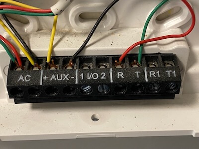
Unpopulated 4 Pin Header
The alarm has spots for two additional headers, but they were empty: A four pin and an eight pin. I started with the four pin header (and, spoiler, never looked at the 8 pin). Using my multimeter, I found the ground pin (#4) and then read 3.3V on each of the remaining. Jackpot! Just a couple days previously I’d been looking at the Microchip PIC24 microcontroller on the Bus Pirate, and seeing a 3.3V line on the alarm panel had me very hopeful it was connected (possibly directly?) to the dsPIC33F that I see on the board.
I’ve done some soldering kits (ex: I’m partway through the 555SE kit and am having a blast). However this is my first time soldering something on a commercial project, and even though I’m nervous I rationalize that even if I totally ruin it, it’s not like the alarm was doing us a lot of good as-is.
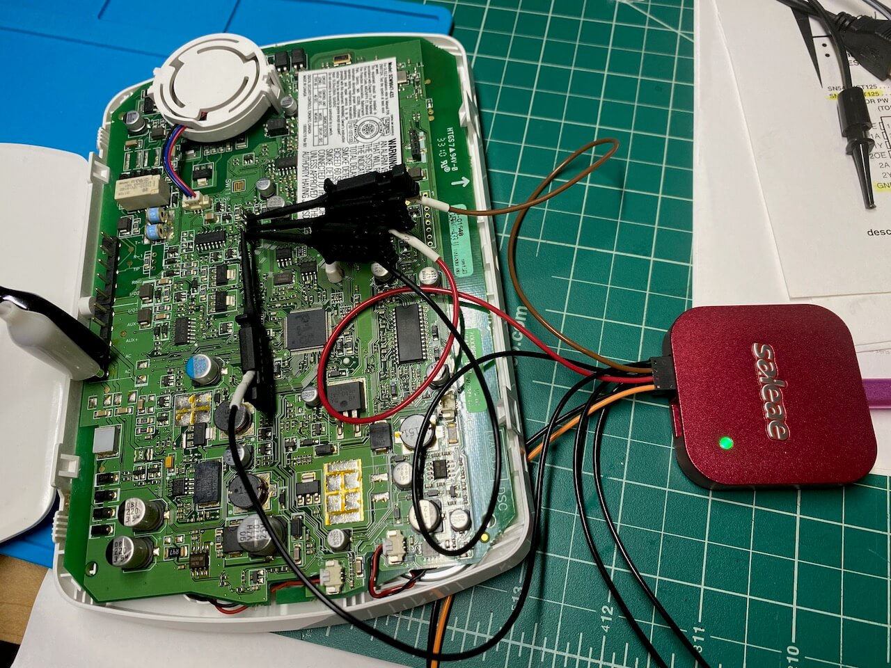
I connect up the Saleae, and take some traces. Pin 1 is a constant 3.3V supply. Pins 2 and 3 both have activity. I’ve been fixated on finding a serial link, and assume I’m seeing both RX and TX from some components, but I cannot figure out the right settings to get a coherent decoding:
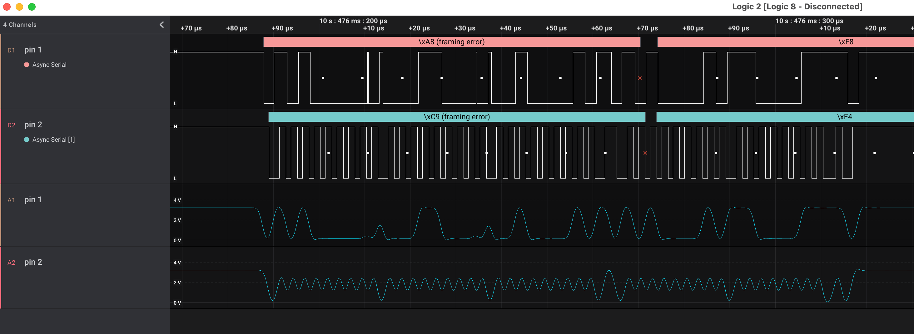
❌UART Serial ✅ I²C
Like I said, I haven’t used the logic analyzer for much, and this is a new hobby. However, having added the analog readings to the display, I realize that “pin 2” 👆 looks suspiciously like a clock signal. In retrospect, it’s visible in the digital too, but 🤦♂️
Ok, so it’s I²C. I’ve done some work with an I²C component already, so this is a puzzle piece I recognize. The I2CDevice class in esphome.io has a very consistent pattern to communicate with I²C chips: write a command (+ optional data) to an address, and then read the response from that address.
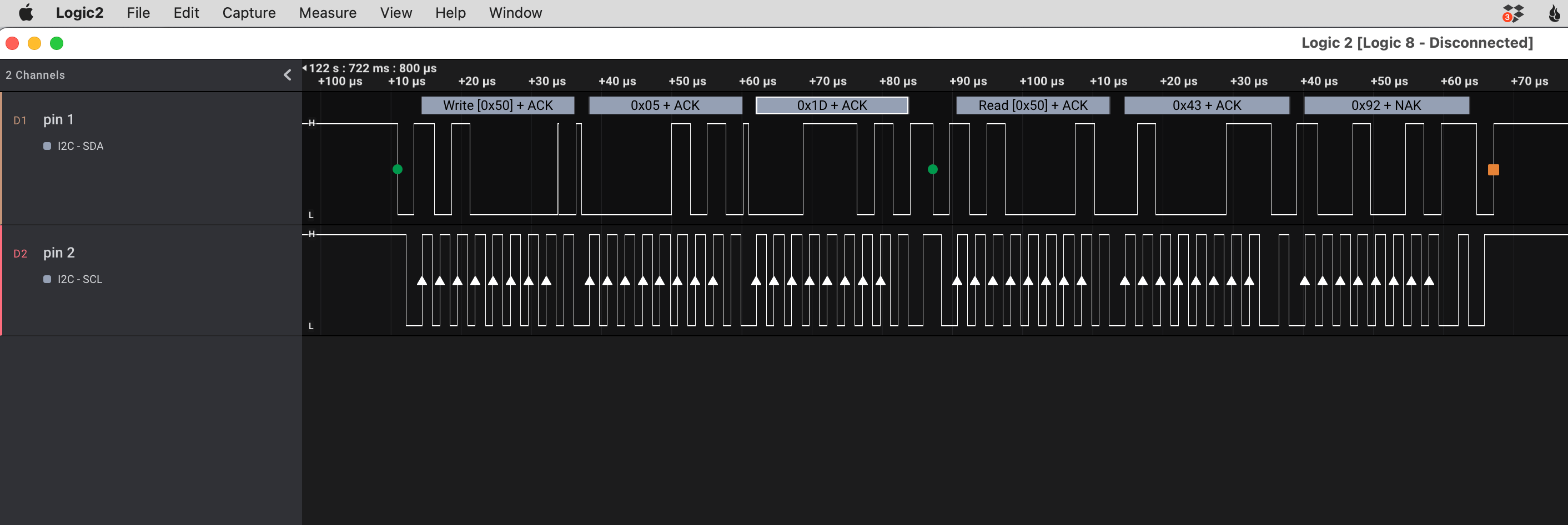
What I see is every single message is addressed to 0x50 and every message is a write followed by a read. Step one, google i2c address 0x50, and TIL there’s a website that shows components with a specific address.
The first suggestion is an EEPROM, and I quickly spot an SO-8 labeled 24C64WP on the alarm circuit board. I almost don’t need to confirm the address that chip uses, this feels right.
💡 Lightbulb!
It really was a lightbulb moment: the realization that I’ve (probably) got access to every single persistent storage read & write that the microcontroller makes, and I can see them on a timeline graph.
Well, sure. The EEPROM is full of binary data, 8 KB of it. There’s a large block of activity after boot, but then it quiets down. How do I provide meaning to the bits moving back and forth?
🤔 what are the odds that the code that checks an Installer Code attempt (I’d been running down a list of “common” installer codes) reads the actual Installer Code during the comparison? It’s got to be worth a shot… It’s the kind of easy-to-make coding error that the various Stripe CTFs drilled home for me.
The expected code is 4 digits long. There are exactly two write/reads with a response length of 4 bytes at the moment I press the last button in my guess, and they’re both four decimal digits (no hex): 0x4392 and 0x0602.
I can scarcely believe it. I try the first one, and I’m in. Days later, I still can’t believe that simply by connecting 3 wires to a very inviting looking location, the alarm panel has told me what the secret code is.
🔐 Security
I achieved my goal! I can now selectively reprogram our system, using the comprehensive documentation in the Installer Guide.
After the elation subsides, I start to wonder about the security. I think it’d be almost trivial to build a device that spams the I²C command to read that specific memory location and display any result received. The wikipedia page for I²C tells me the protocol supports multiple controllers on a single bus. Could you enter someone’s house, pop the alarm panel off the wall, and take the installer code after a momentary contact to these header slots? Any firmware changes or model differences might require looking in multiple memory slots, but it seems like the problem space goes from 104 to something a lot smaller.
I haven’t checked if the installer code will disarm an active alarm. That’s okay, just pull the master code instead and/or additionally. Having unencrypted, un-obfuscated secrets read from memory on demand, combined with an oracle for whether or not I’ve found the correct bits means I think it’s easy to find the location (and contents) of those secrets.
Tampering and Monitoring
Now, this blog post moves into speculation. It’s interesting to ponder given my training on computer security, although I’m not going to do it justice here. I think a solution to this physical insecurity has two parts.
The Hackaday teardown of a SCW9057 pointed out the first half: the alarm panel has a switch that’ll detect when it’s pulled away from the wall. So the software has a method to detect physical tampering. However, “tampering” is also how the installer configures the device through PC-Link, or how the panel’s battery is replaced. The alarm panel cannot have a fatal reaction to tampering, like you might with a credit card reader (where it’s reasonable to wipe the private key material if the case is opened).
The second half is remote monitoring. If, and I don’t know if it’s part of the protocol used, the monitoring service can identify and handle untrustworthy alarm panels, I think it’s possible to provide pretty good security. A panel is trustworthy until it’s tampered with, and then the state is unknown. You’d need some out-of-band method to restore trust in it — an alarm panel reporting “just kidding, false alarm, they entered the Installer code” is nowhere near sufficient. A phone call to the homeowner who provides a passphrase acknowledging the panel was removed and things are fine seems closer, but your home owner may not be able to detect compromised hardware.
I think there’s still a hole in the system:
- alarm is disarmed (ex: homeowner is home, evil maid finds himself alone with the panel)
- communication to monitoring service is cut
- alarm is tampered with, Installer and/or Master codes are read
- spoof <whatever> signal is necessary to tell the panel the tampering was fine
- dial the wrong number, connect fake modem, whatever
- reconnect monitoring service
Since the alarm had no chance to alert the monitoring service, if the tampering fault can be cleared before reconnecting, the alarm panel believes the monitoring service is aware of the issue.
Can that be solved? Maybe something like a write-only, increment-only tamper counter. When the panel checks in with the monitoring service it notices the discrepancy, and can take action. If the panel never checks in again, the service can also take action.
Secrets in the Clear
Is this just how embedded programming works? Secret values sent in the clear from storage to the microcontroller? I suspect often the answer is yes. It’s possible to do better, and I’ve got a couple ATECC608 breakouts I’ve been meaning to play with. As a (primarily) iOS developer, the opportunity to poke directly at a Secure Element is interesting. If the alarm panel had one of these chips, the microcontroller could securely ask “is the installer code ABCD?”, as well as authenticate itself to the monitoring service.
I’m both happy the ATECC chips exist and are pretty cheap, but also sad that one of their primary use cases is for authenticated printer ink cartridges.
👀 DIY Remote Monitoring
I think I’ve got three main options for DIY remote monitoring.
- Monitor sensors independent of the alarm system (aka Home Assistant with something like this). This basically ignores the panel, and would use our internet connection to alert.
- Use existing cellular modem, contact a DIY monitoring server/receiver. It looks like the protocol used between the alarm system and the central monitoring system is documented, and there are existing open-source solutions. I think using Twilio allows me to receive calls from the alarm and turn them into alerts. This uses cellular (can’t cut the hard line), it has a battery back-up (still works if the power is out), and is cheaper than professional monitoring.
- Create a fake modem. I can replace the existing cellular modem, and just use our home internet to send out the alerts. We retain the alarm system arm/disarm UX, but would be vulnerable to internet outages.
🏡 Neighborhood Watch
We actually have two alarm systems. The first one dates back to the 80s, and has a big bell mounted externally to the house (with tamper sensors, naturally). The second one uses the SCW9047, wireless sensors, and a cellular modem for remote monitoring.
I haven’t yet discovered what the old alarm bell sounds like, but I’m looking forward to using it as a deterrent, regardless of how I end up implementing remote monitoring.